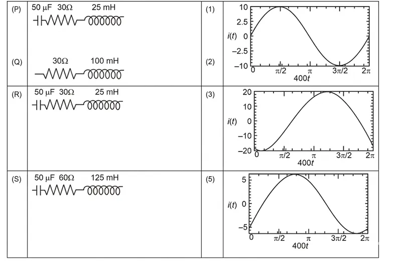
A circuit with an electrical load having impedance Z is connected with an AC source as shown in the diagram. The source voltage varies in time as V(t) = 300 sin(400t) V, where t is time in s. List-I shows various options for the load. The possible currents i(t) in the circuit as a function of time are given in List-II.

Choose the option that describes the correct match between the entries in List-I to those in List-II.
Correct Answer :
P→3, Q→5, R→2, S→1
Solution :
The given AC source voltage is:
From this expression, we can identify the following system parameters:
- Peak source voltage:
- Angular frequency:
Let us analyze each load configuration in List-I one by one:
1. Analysis of Load (P):
In the load diagram (P), a capacitor of capacitance and an inductor of inductance are bypassed (short-circuited) by a connecting wire, leaving only the resistor in the active circuit path.
Thus, the load is purely resistive:
For a purely resistive circuit, the current and voltage are in phase ().
The peak current is:
The instantaneous current is:
This corresponds to graph (3) in List-II (in-phase waveform with peak value of 10 A).
Hence, P → 3.
2. Analysis of Load (Q):
In configuration (Q), a resistor and an inductor are connected in series.
The inductive reactance is:
The total impedance of this RL series circuit is:
The peak current is:
In an RL circuit, the current lags the voltage by a phase angle :
Thus, the instantaneous current is:
At , .
This corresponds to graph (5) in List-II, which has a peak of 6 A and is negative at .
Hence, Q → 5.
3. Analysis of Load (R):
In configuration (R), a capacitor , resistor , and inductor are connected in series.
The reactances are:
The net reactance is:
(capacitive)
The impedance of this RLC circuit is:
The peak current is:
Since , the current leads the voltage by a phase angle :
Thus, the instantaneous current is:
At , .
This matches graph (2) in List-II (peak of 6 A and positive at ).
Hence, R → 2.
4. Analysis of Load (S):
In configuration (S), a capacitor , resistor , and inductor are connected in series.
The reactances are:
Since , the circuit is in resonance.
The impedance is purely resistive:
The phase difference is because the net reactance is zero.
The peak current is:
The instantaneous current is:
This corresponds to graph (1) in List-II (in-phase waveform with peak value of 5 A).
Hence, S → 1.
Combining these matches gives:
P → 3, Q → 5, R → 2, S → 1
Access expert-curated educational resources and study materials—completely free.
Create, conduct, and manage professional online assessments with Mindyard. Perfect for teachers and institutes.
Copyright © 2026 Mindyard. All Rights Reserved.