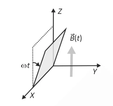
A conducting square loop initially lies in the XZ-plane with its lower edge hinged along the X-axis.Only in the region y ≥ 0, there is a time dependent magnetic field along Z-direction: B(t) = B₀ cos(ωt) k̂ where B₀ is a constant. The magnetic field is zero elsewhere. At t = 0, the loop starts rotating with constant angular speed ω about the X-axis in clockwise direction (as seen from +X-axis).Ignoring self-inductance and gravity, which plot correctly represents the induced emf (V) vs time?
Options
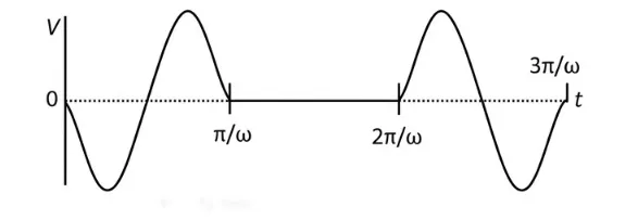
Correct Answer :
Solution :
To determine the correct plot of the induced electromotive force () versus time (), we analyze the motion of the loop and the magnetic field region step-by-step:
1. Identifying the Region and Magnetic Field:
The magnetic field is given as:
for
for
2. Motion of the Loop:
Initially at , the loop lies in the XZ-plane (). It starts rotating about the X-axis clockwise (as seen from the positive X-axis) with a constant angular velocity .
- During the time interval , the loop rotates through the region .
- During the time interval , the loop is in the region where the magnetic field is zero.
3. Magnetic Flux through the Loop:
Let be the area of the square loop.
At time , when the loop is in the region , the angle between the normal vector of the loop and the Z-axis (direction of the magnetic field ) is .
The magnetic flux is:
4. Induced EMF ():
By Faraday's law of induction, the induced electromotive force is:
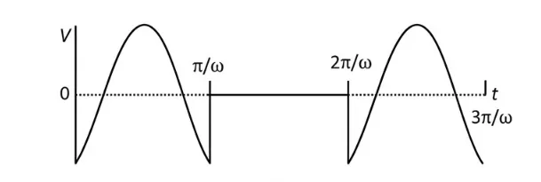
Evaluating this expression over key times:
- At , (negative non-zero value).
- At , .
- At , (maximum positive value).
- At , .
- At , .
For the interval :
The loop is in the region where the magnetic field is zero, meaning and thus .
This periodic behavior of matches the plot shown in Image 1.
Access expert-curated educational resources and study materials—completely free.
Create, conduct, and manage professional online assessments with Mindyard. Perfect for teachers and institutes.
Copyright © 2026 Mindyard. All Rights Reserved.