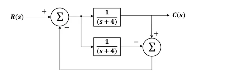
A control system is shown in the Figure. Which option represents the correct transfer function of the system?
Correct Answer :
Solution :
The correct option/answer is:
Step-by-Step Derivation and Analysis:
1. Identifying the Components from the Block Diagram:
By analyzing the provided control system diagram, we observe the following signals and blocks:
- Input signal:
- Output signal:
- First Summing Junction (on the left): Takes the input with a positive sign (+) and the feedback signal with a negative sign (-).
- Forward path block:
- Feedback path block:
- Second Summing Junction (on the right): Combines the output of the upper path with a positive sign (+) and the output of the lower path feedback block with a negative sign (-).
2. Formulating the System Equations:
Let be the output of the first summing junction.
The output is the output of the upper forward path:
This can be rewritten to express in terms of :
For a standard feedback system with a forward path and a unity negative feedback loop , the closed-loop transfer function is defined by the relation:
Substituting and into the equation:
3. Simplifying the Transfer Function:
Multiply the numerator and denominator by :
Expand the quadratic term in the denominator:
Now, add 1 to the expanded form:
Thus, the final closed-loop transfer function of the control system is:
Access expert-curated educational resources and study materials—completely free.
Create, conduct, and manage professional online assessments with Mindyard. Perfect for teachers and institutes.
Copyright © 2026 Mindyard. All Rights Reserved.