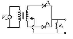
A full wave rectifier circuit with diodes (D1) and (D2) is shown in the figure. If input supply voltage V in = 220sin ( 100πt ) volt, then at t = 15 m sec
Correct Answer :
D1 is reverse biased, D2 is forward biased
Solution :
The correct answer is: D1 is reverse biased, D2 is forward biased
Step-by-step Explanation:
1. Identify the given parameters:
The input voltage to the primary of the transformer is given by:
We need to determine the state of the diodes D1 and D2 at time:
2. Calculate the phase angle at the given instant:
Substitute the value of t into the angular argument of the sine function:
3. Determine the sine value and the input voltage:
Calculate the value of the sine function at this phase:
Now, find the value of the input voltage:
Since the input voltage is negative, the AC source is in its negative half-cycle.
4. Analyze the diode biasing:
The schematic shows a center-tapped transformer configuration:
- During the positive half-cycle (Vin > 0), the upper terminal of the secondary winding is at a positive potential and the lower terminal is at a negative potential relative to the center tap. This makes the anode of D1 positive (forward biased) and the anode of D2 negative (reverse biased).
- During the negative half-cycle (Vin < 0), which occurs at t = 15 ms, the polarity across the secondary winding reverses. The upper terminal of the secondary winding becomes negative relative to the center tap, and the lower terminal becomes positive.
Consequently:
- The anode of diode D1 is connected to a negative potential, making it reverse biased.
- The anode of diode D2 is connected to a positive potential, making it forward biased.
Access expert-curated educational resources and study materials—completely free.
Create, conduct, and manage professional online assessments with Mindyard. Perfect for teachers and institutes.
Copyright © 2026 Mindyard. All Rights Reserved.