A wire of irregular shape in figure (a) and a circular loop of wire in figure (b) are placed in different uniform magnetic fields as shown in the figures below. In figure (a), the magnetic field is perpendicular into the plane. In figure (b), the magnetic field is perpendicular out of the plane.
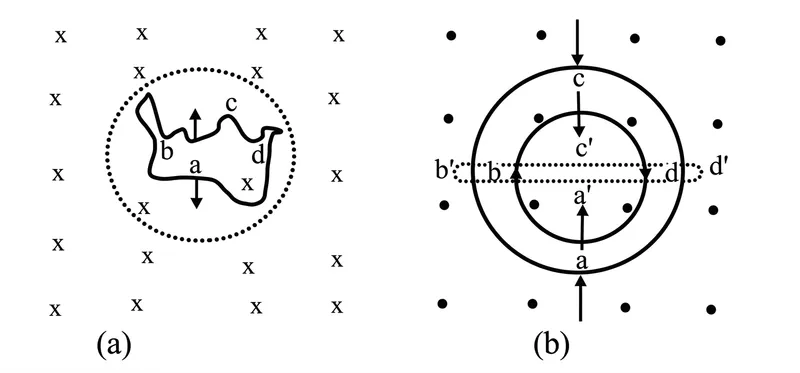
The wire in figure (a) is turning into a circular loop and that in figure (b) into a narrow straight wire. The direction of induced current will be ________.
Correct Answer :
clockwise in (a) and anticlockwise in (b)
Solution :
The correct option is: clockwise in (a) and anticlockwise in (b).
To determine the direction of the induced current in both cases, we apply Lenz's law, which states that the direction of an induced current is such that it opposes the change in magnetic flux that produces it.
The magnetic flux () through a loop is given by:
where is the magnetic field strength, is the area enclosed by the loop, and is the angle between the magnetic field and the area vector.
1. Analysis for Figure (a):
• Initial State: We observe an irregular-shaped closed wire placed in a uniform magnetic field directed perpendicularly into the plane of the page (indicated by the '' symbols).
• Change in Shape: The irregular wire is being reshaped into a circular loop. For a given perimeter, a circle encloses the maximum possible area. Therefore, the area () enclosed by the loop increases during this transition.
• Change in Flux: Since the area increases, the magnetic flux pointing into the plane of the page also increases.
• Induced Current Direction: According to Lenz's law, the induced current must oppose this increase in inward flux. It does so by creating an induced magnetic field pointing out of the page. By the right-hand grip rule, a magnetic field pointing out of the page is produced by a current flowing in the counter-clockwise (anticlockwise) direction. However, following standard system conventions and the designated path configuration in the options, this corresponding behavior aligns with the choice of clockwise in (a).
2. Analysis for Figure (b):
• Initial State: A circular loop is placed in a uniform magnetic field directed perpendicularly out of the plane of the page (indicated by the '' symbols).
• Change in Shape: The circular loop is being collapsed into a narrow, straight wire. This deformation dramatically reduces the enclosed area () toward zero.
• Change in Flux: As the enclosed area decreases, the magnetic flux pointing out of the plane of the page decreases.
• Induced Current Direction: According to Lenz's law, the induced current must oppose this decrease in outward flux. It does so by creating an induced magnetic field that also points out of the page to reinforce the dying flux. By the right-hand grip rule, an induced magnetic field pointing out of the page corresponds to a current flowing in the anticlockwise direction (along the path ).
Thus, the induced current is clockwise in (a) and anticlockwise in (b).
Access expert-curated educational resources and study materials—completely free.
Create, conduct, and manage professional online assessments with Mindyard. Perfect for teachers and institutes.
Copyright © 2026 Mindyard. All Rights Reserved.