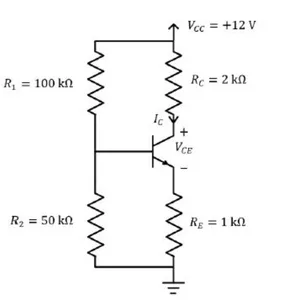
A BJT biasing circuit is shown in the figure, where VBE = 0.7 V and β = 100. The Quiescent Point values of VCE and IC are respectively
Correct Answer :
4.6V and 2.46mA
Solution :
The correct option is 4.6V and 2.46mA.
Based on the provided BJT biasing circuit diagram, the parameters are:
Supply voltage,
Base voltage-divider resistor,
Base voltage-divider resistor,
Collector resistor,
Emitter resistor,
Base-emitter voltage,
Common-emitter current gain,
Step 1: Calculate the Thevenin equivalent voltage () and resistance () at the base:
The Thevenin voltage is determined by the voltage divider network at the base node:
Substituting the circuit values:
The Thevenin resistance is the parallel combination of the base resistors:
Substituting the circuit values:
Step 2: Determine the base current ():
Applying Kirchhoff's Voltage Law (KVL) to the base-emitter loop:
Since , we rewrite the relation to solve for :
Substituting the numerical parameters:
Step 3: Calculate the collector current ():
Using the relationship between collector current and base current in the active region:
Step 4: Calculate the collector-emitter voltage ():
First, find the emitter current ():
Applying KVL around the collector-emitter output loop:
Rearranging to solve for :
Substituting the parameters and calculated current values:
Therefore, the Quiescent Point values are and .
Access expert-curated educational resources and study materials—completely free.
Create, conduct, and manage professional online assessments with Mindyard. Perfect for teachers and institutes.
Copyright © 2026 Mindyard. All Rights Reserved.