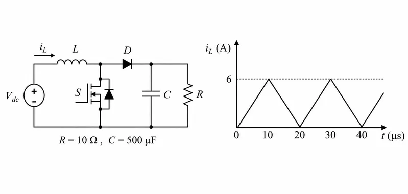
Consider the boost converter circuit shown. In steady state, the inductor cur rent rises linearly from 0 A to 6 A in the first 10 µs and then falls linearly from 6 A to 0 A in the next 10 µs. The load resistance R is 10 Ω. What is the input voltage Vdc?
Correct Answer :
7.5 V
Solution :
The correct option is 7.5 V.
1. Identify the circuit and waveform parameters from the image:
From the circuit diagram and the inductor current waveform in the image, we can extract the following values:
- Load resistance,
- Peak inductor current,
- Inductor current rise time (switch ON time),
- Inductor current fall time (switch OFF time),
- Total switching period,
2. Apply the inductor volt-second balance:
In steady-state operation, the average voltage across the inductor over one complete period is zero:
Substitute the values of and :
3. Calculate the average load current:
In steady state, the average current through the output capacitor is zero. Therefore, the average load current must equal the average current through the diode .
Since the diode only conducts during the off-period, the diode current waveform is a triangle with a peak value of and duration :
Substitute the values:
4. Find the average output voltage and input voltage:
Using Ohm's Law, the average output voltage across the resistor is:
Using the relation from step 2, we solve for :
Access expert-curated educational resources and study materials—completely free.
Create, conduct, and manage professional online assessments with Mindyard. Perfect for teachers and institutes.
Copyright © 2026 Mindyard. All Rights Reserved.