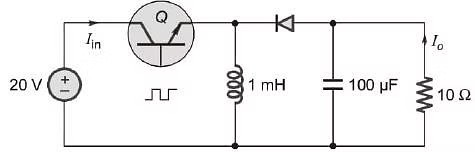
Consider the buck-boost converter shown. Switch Q is operating at 25 kHz and 0.75 duty-cycle. Assume diode and switch to be ideal. Under steady-state condition, the average current flowing through the inductor is ______ A.
Correct Answer :
Solution :
The correct answer is 24.
Based on the provided circuit diagram, we can identify the following components and parameter values:
- Supply voltage,
- Inductance,
- Capacitance,
- Load resistance,
- Switching frequency,
- Duty cycle,
Here is the circuit schematic of the buck-boost converter:
Step 1: Calculate the output voltage () of the buck-boost converter
For an ideal buck-boost converter operating under steady-state conditions, the relationship between the average output voltage magnitude and the supply voltage is given by:
Substituting the given values:
Step 2: Calculate the average load current ()
Using Ohm's law, the average current flowing through the load resistor is:
Substituting the calculated load voltage and resistance:
Step 3: Calculate the average inductor current ()
In a buck-boost converter, the inductor is connected to the load only during the off-state of the switch, which represents a fraction of the total switching period. Therefore, the relationship between the average load current and the average inductor current is:
Substituting the values:
Access expert-curated educational resources and study materials—completely free.
Create, conduct, and manage professional online assessments with Mindyard. Perfect for teachers and institutes.
Copyright © 2026 Mindyard. All Rights Reserved.