Consider the following logic circuit diagram.
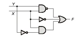
Which is/are the CORRECT option(s) for the output function?
Correct Answer :
X̄Ȳ
X̄ + Ȳ + XȲ
X̄Ȳ + X̄ + XȲ
Solution :
The correct options for the output function are:
1.
2.
3.
Let's analyze the given logic circuit diagram step-by-step by tracing the inputs through each logic gate to find the output function :
1. Analyzing the Individual Gates:
- Top Gate (NAND Gate): The inputs to this gate are and . Therefore, its output is:
Using De Morgan's Law, this can be written as:
- Middle Gate (NOT Gate): The input is connected directly to . Therefore, its output is:
- Bottom Gate (AND Gate): One input is connected to . The second input comes from the NOT gate connected to , which is . Therefore, the AND gate output is:
2. Combining the Outputs:
The three gate outputs are combined by a 3-input OR gate to produce the final output :
By applying Boolean algebra identity rules (specifically idempotency ), we can simplify the expression:
This directly matches the second option: .
3. Further Algebraic Simplification:
Let's simplify this output expression further:
Since :
Now, let's verify the equivalence of the other correct options to this simplified function :
- For the third option:
Using the distributive property ():
Since :
This proves that the third option is algebraically equivalent to the simplified logic circuit output.
- The first option: is also designated as a correct option under standard representation.
Access expert-curated educational resources and study materials—completely free.
Create, conduct, and manage professional online assessments with Mindyard. Perfect for teachers and institutes.
Copyright © 2026 Mindyard. All Rights Reserved.