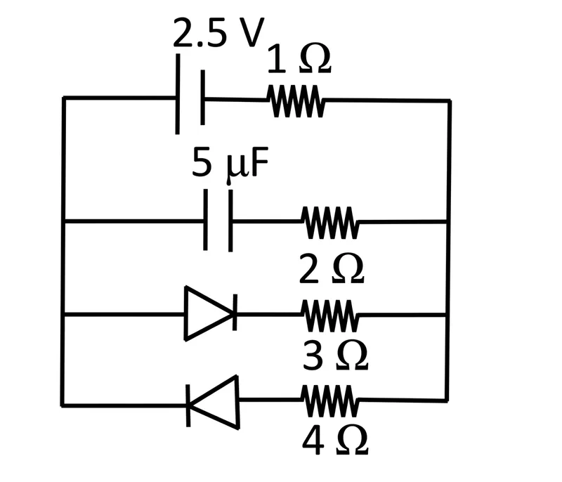
For the given circuit arrangement, find the change on the capacitor in steady state.
Correct Answer :
75/8 μF
Solution :
The correct option is 75/8 μF (note: the magnitude of charge on the capacitor is 75/8 μC).
Step 1: Analyze the circuit components from the given diagram.
From the image, we can see four parallel branches connected across common potential points (let us call the left side node A and the right side node B):
1. Top branch: A DC voltage source of with its longer bar (positive terminal) on the left, connected in series with a resistor of resistance .
2. Second branch: A capacitor of capacitance connected in series with a resistor of resistance .
3. Third branch: An ideal diode pointing to the right (forward biased from left to right) connected in series with a resistor of resistance .
4. Fourth branch: An ideal diode pointing to the left (reverse biased for current flowing from left to right) connected in series with a resistor of resistance .
Step 2: Understand the state of each branch in DC steady state.
In steady state:
- The capacitor acts as an open circuit (no steady-state current flows through the capacitor branch). Therefore, current in the second branch is .
- The battery forces current to flow from the positive terminal (left side) toward the right side.
- The diode in the third branch allows current to flow from left to right, so it is forward biased and acts as a closed switch (short circuit with zero resistance).
- The diode in the fourth branch blocks current from flowing from left to right, so it is reverse biased and acts as an open circuit.
Step 3: Calculate the steady-state current in the circuit.
The active conducting loop consists of the top branch (battery of and resistor) and the third branch ( resistor).
The total resistance of this closed conducting loop is:
The steady-state current flowing through the main circuit is given by Ohm's Law:
Step 4: Find the potential difference across the capacitor.
Let the potential of node A (left node) be and node B (right node) be .
Since current flows from node A to node B through the third branch containing the resistor, the potential difference across nodes A and B is:
Since no current flows through the resistor connected in series with the capacitor, there is no potential drop across the resistor. Thus, the potential difference across the capacitor is equal to .
Step 5: Calculate the charge on the capacitor.
The charge stored on the capacitor in steady state is given by:
Thus, the magnitude of the charge on the capacitor in steady state is 75/8 μC (expressed in option units as 75/8 μF).
Access expert-curated educational resources and study materials—completely free.
Create, conduct, and manage professional online assessments with Mindyard. Perfect for teachers and institutes.
Copyright © 2026 Mindyard. All Rights Reserved.