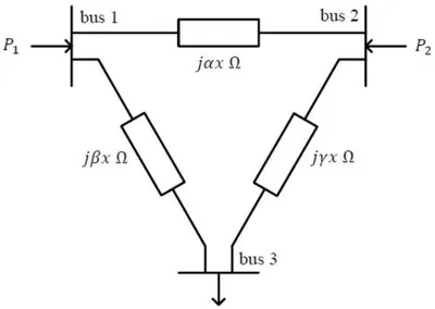
For the three-bus lossless power network shown in the figure, the voltage magnitudes at all the buses are equal to 1 per unit (pu), and the differences of the voltage phase angles are very small. The line reactances are marked in the figure, where α, β, γ and x are strictly positive. The bus injections P1 and P2 are in pu. If P1 = mP2, where m > 0, and the real power flow from bus 1 to bus 2 is 0 pu, then which one of the following options is correct?
Correct Answer :
γ = m β
Solution :
The correct option is:
Step-by-Step Explanation:
1. Analyze the Given Network from the Image:
From the schematic of the three-bus lossless power network:
- The line reactance between bus 1 and bus 2 is
.
- The line reactance between bus 1 and bus 3 is
.
- The line reactance between bus 2 and bus 3 is
.
- The voltage magnitude at all buses is
.
- The phase angles at bus 1, bus 2, and bus 3 are
,
, and
respectively, and their differences are very small.
2. Apply DC Power Flow Approximation:
For a lossless system with flat voltage profile (1 pu) and small angle differences, the active power flow
from bus
to bus
is given by:
3. Condition for Zero Power Flow between Bus 1 and Bus 2:
We are given that the real power flow from bus 1 to bus 2 is 0 pu. Therefore:
Since
and
are strictly positive, this directly implies:
4. Formulate Power Injection Equations:
Using nodal equations, the power injected at bus 1 (
) is:
Similarly, the power injected at bus 2 (
) is:
Substituting
into the equation for
:
5. Relate the Injections:
We are given that
. Taking the ratio of
to
:
Substitute
into the equation:
Rearranging terms, we obtain:
Access expert-curated educational resources and study materials—completely free.
Create, conduct, and manage professional online assessments with Mindyard. Perfect for teachers and institutes.
Copyright © 2026 Mindyard. All Rights Reserved.