he circuit shown in the figure contains an inductor 𝐿, a capacitor 𝐶0, a resistor 𝑅0 and an ideal battery. The circuit also contains two keys K1 and K2. Initially, both the keys are open and there is no charge on the capacitor. At an instant, key K1 is closed and immediately after this the current in 𝑅0 is found to be 𝐼1. After a long time, the current attains a steady state value 𝐼2. Thereafter, K2 is closed and simultaneously K1 is opened and the voltage across 𝐶0 oscillates with amplitude 𝑉0 and angular frequency 𝜔0.
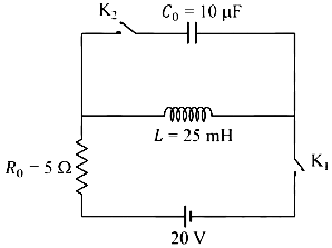
Match the quantities mentioned in List-I with their values in List-II and choose the correct option.
| List-I | List-II |
| (P) The value of 𝐼1 in Ampere is | (1) 0 |
| (Q) The value of 𝐼2 in Ampere is | (2) 2 |
| (R) The value of 𝜔0 in kilo-radians/s is | (3) 4 |
| (S) The value of 𝑉0 in Volt is | (4) 20 |
| (5) 200 |
Correct Answer :
P → 1; Q → 3; R → 2; S → 5
Solution :
Correct Option: P → 1; Q → 3; R → 2; S → 5
To solve this problem, we analyze the circuit configurations step-by-step using the values given in the circuit diagram:
- Battery Voltage,
- Resistor,
- Inductor,
- Capacitor,
Step 1: Finding (Immediately after closing )
Initially, both switches and are open, and there is no current in the inductor. At , switch is closed while remains open. An inductor opposes any sudden change in current. Since the current through the inductor was just before closing the switch, it must remain immediately after closing the switch:
Because the capacitor branch is open, the current flowing through is the same as the current through the inductor. Thus, the initial current is:
This corresponds to P → 1.
Step 2: Finding (After a long time in steady state)
After a long time, the circuit reaches a steady state. In a DC circuit, an inductor acts as a short circuit (zero resistance) at steady state. The current flows from the battery, through the resistor , and through the shorted inductor back to the battery. The steady-state current is:
This corresponds to Q → 3.
Step 3: Finding the angular frequency
When is closed and is opened simultaneously, the battery and the resistor are disconnected from the loop containing the inductor and the capacitor . This forms a closed, parallel LC oscillating circuit. The angular frequency of oscillation is:
Substituting the given values:
This corresponds to R → 2.
Step 4: Finding the amplitude of the voltage oscillation
At the instant is opened and is closed, the current flowing in the inductor is and the charge on the capacitor is zero. The total energy stored in the LC circuit is equal to the initial magnetic energy of the inductor:
During the oscillation, the maximum voltage across the capacitor occurs when all the electromagnetic energy is stored in the electric field of the capacitor:
Solving for :
Substituting the values:
This corresponds to S → 5.
Access expert-curated educational resources and study materials—completely free.
Create, conduct, and manage professional online assessments with Mindyard. Perfect for teachers and institutes.
Copyright © 2026 Mindyard. All Rights Reserved.