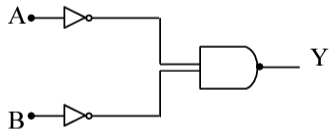
Identify the logic gate given in the circuit :
Correct Answer :
OR - gate
Solution :
The correct answer is OR gate.
Looking at the circuit diagram carefully, the following components are visible:
- Input A is fed into a NOT gate (inverter — shown as a triangle with a small circle/bubble at the output).
- Input B is fed into another NOT gate (inverter).
- The outputs of both NOT gates (A̅ and B̅) are then fed as inputs into a NAND gate (AND gate symbol with a bubble at its output).
- The final output is Y.
So the Boolean expression for the output Y can be written as:
In cleaner notation, the output of the NAND gate applied to A̅ and B̅ is:
That is: Y = NOT( NOT(A) · NOT(B) )
Step 1: Apply the inner NOT gates.
The two NOT gates produce A̅ (NOT A) and B̅ (NOT B).
Step 2: Apply the NAND operation on A̅ and B̅.
A NAND gate gives the complement of (A AND B). So applied to A̅ and B̅:
Step 3: Apply De Morgan's Theorem.
De Morgan's theorem states:
Applying this to our expression (where X = A̅ and Z = B̅):
Step 4: Apply the double negation law (NOT NOT X = X).
The double complement of any variable returns the variable itself:
Therefore:
Conclusion: The output Y = A + B, which is exactly the Boolean expression for an OR gate.
This circuit — two NOT gates feeding into a NAND gate — is a well-known implementation of an OR gate using only NAND-based logic, consistent with De Morgan's equivalence theorem. The circuit is therefore equivalent to an OR gate.
Truth Table Verification:
| A | B | A̅ | B̅ | Y = NAND(A̅, B̅) = A + B |
|---|---|---|---|---|
| 0 | 0 | 1 | 1 | 0 |
| 0 | 1 | 1 | 0 | 1 |
| 1 | 0 | 0 | 1 | 1 |
| 1 | 1 | 0 | 0 | 1 |
The output column matches exactly the truth table of an OR gate, confirming the answer is the OR gate.
Access expert-curated educational resources and study materials—completely free.
Create, conduct, and manage professional online assessments with Mindyard. Perfect for teachers and institutes.
Copyright © 2026 Mindyard. All Rights Reserved.