In Circuit-1 and Circuit-2 shown in the figures, , and . and are the power dissipations in Circuit-1 and Circuit-2 when the switches and are in open conditions, respectively. and are the power dissipations in Circuit-1 and Circuit-2 when the switches and are in closed conditions, respectively.
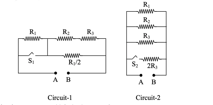
Which of the following statements (s) is (are) correct ?
Correct Answer :
When a voltage source of 6V is connected across A and B in both circuits, P1 < P2
When a constant current source of 2 Amp is connected across A and B in both circuits, P1 > P2
When a voltage source of 6V is connected across A and B in Circuit-1, Q1 > P1.
Solution :
The correct statements are:
(1) When a voltage source of 6V is connected across A and B in both circuits, P1 < P2
(2) When a constant current source of 2 Amp is connected across A and B in both circuits, P1 > P2
(3) When a voltage source of 6V is connected across A and B in Circuit-1, Q1 > P1
First, let us carefully read the circuit diagrams from the image.
Circuit-1 (Switch S1 open): The top branch has R1, R2, R3 all in series. S1 is connected in parallel with R1 (it bridges the two nodes at either end of R1). A resistor R1/2 is in the bottom branch connected between the middle node (between R1 and R2) and terminal A/B side. When S1 is open, no current flows through S1 or R1/2. The circuit between A and B is simply R1 + R2 + R3 in series.
Circuit-2 (Switch S2 open): R1, R2, R3 are three separate parallel branches between A and B. S2 is in series with 2R3 forming a fourth branch — but since S2 is open, that branch carries no current. So only R1, R2, R3 in parallel remain.
Now we also need the equivalent resistances when the switches are closed.
Circuit-1 (Switch S1 closed): When S1 is closed, it short-circuits R1, so no current flows through R1. Also, the bottom branch with R1/2 is now connected (since S1 closes the path). The current now flows through S1 (zero resistance) in parallel with R1, effectively making the parallel combination = 0 Ω. Then in series with R2 and R3, we also have R1/2 in the bottom branch. Let us be precise: S1 shorts R1 at the top-left, and R1/2 connects the node between R1 and R2 down to the bottom rail. With S1 closed, the node to the left of R2 is connected directly to the bottom rail through S1. This means R1/2 becomes connected between the same node (junction of R1 and R2) and the bottom rail — i.e., R1/2 is now in parallel with R2 + R3.
With R1 = 1 Ω, so R1/2 = 0.5 Ω. R2 + R3 = 2 + 3 = 5 Ω.
Circuit-2 (Switch S2 closed): Now all four branches are active in parallel: R1, R2, R3, and 2R3. With R3 = 3 Ω, so 2R3 = 6 Ω.
Let us now compile the four equivalent resistances:
Statement (1): Voltage source of 6V connected across A and B. Compare P1 and P2 (switches open).
Power dissipated by a voltage source V across resistance R is:
Since the voltage is fixed at 6V, a larger equivalent resistance means less power dissipated.
Since 6 W < 66 W, we get P1 < P2. ✓ Statement (1) is CORRECT.
Statement (2): Constant current source of 2 A connected across A and B. Compare P1 and P2 (switches open).
Power dissipated by a constant current source I through resistance R is:
Since the current is fixed at 2 A, a larger resistance means more power dissipated.
Since 24 W > 2.18 W, we get P1 > P2. ✓ Statement (2) is CORRECT.
Statement (3): Voltage source of 6V across A and B in Circuit-1. Compare Q1 (switch closed) and P1 (switch open).
When S1 is closed in Circuit-1:
We already computed P1 = 6 W. Since 79.2 W > 6 W, Q1 > P1. ✓ Statement (3) is CORRECT.
This makes intuitive sense: closing S1 drastically reduces the total resistance (from 6 Ω to 5/11 Ω ≈ 0.45 Ω), so with the same 6V supply, much more current flows and power dissipation increases enormously.
Statement (4): Constant current source of 2 A across A and B in both circuits. Compare Q2 (S2 closed) and Q1 (S1 closed).
With 2 A constant current:
Since 2 W > 1.818 W, we get Q2 > Q1, meaning Q2 < Q1 is FALSE. ✗ Statement (4) is INCORRECT.
Summary Table:
| Statement | Comparison | Values | Result |
|---|---|---|---|
| (1) 6V source, switches open | P1 < P2 | 6 W < 66 W | ✓ Correct |
| (2) 2A source, switches open | P1 > P2 | 24 W > 2.18 W | ✓ Correct |
| (3) 6V source, Circuit-1 closed | Q1 > P1 | 79.2 W > 6 W | ✓ Correct |
| (4) 2A source, both closed | Q2 < Q1 | 2 W > 1.82 W | ✗ Incorrect |
Therefore, statements (1), (2), and (3) are correct.
Access expert-curated educational resources and study materials—completely free.
Create, conduct, and manage professional online assessments with Mindyard. Perfect for teachers and institutes.
Copyright © 2026 Mindyard. All Rights Reserved.