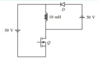
In the dc-dc converter circuit shown, switch Q is switched at a frequency of 10 kHz with a duty ratio of 0.6. All components of circuit are ideal and the initial current in the inductor is zero. Energy stored in the inductor in mJ (rounded off to 2 decimal places) at the end of 10 complete switching cycles is ______.
Correct Answer :
Solution :
The correct answer is 5.
1. Understanding the Circuit Parameters from the Given Image:
From the provided circuit diagram, we can identify the following components and parameters:
- Input DC Voltage (): 50 V
- Inductance (): 10 mH = 10 × 10-3 H
- Diode connected in series with another 50 V source across the inductor branch.
- Switching frequency (): 10 kHz
- Duty ratio (): 0.6
- Initial inductor current (): 0 A
2. Time Period Calculations:
The total switching time period () is given by:
The ON-time of switch Q () during each cycle is:
The OFF-time of switch Q () during each cycle is:
3. Operation Analysis per Cycle:
Mode 1: Switch Q is ON ()
When switch Q is closed, the left 50 V source is connected directly across the 10 mH inductor. The diode is reverse biased by the secondary source.
The voltage across the inductor is .
The increase in inductor current during is:
Mode 2: Switch Q is OFF ()
When switch Q turns off, the inductor current freewheels through diode and the right-hand 50 V source.
The voltage across the inductor reverses such that .
The decrease in inductor current during is:
4. Net Current Change per Cycle:
The net change in current per switching cycle is:
5. Current after 10 Complete Switching Cycles:
Since the initial current is , the current at the end of 10 complete switching cycles will be:
6. Energy Stored in the Inductor:
The energy stored in an inductor is given by the formula:
Substituting the values of and :
Thus, the energy stored in the inductor at the end of 10 complete switching cycles is 5 mJ.
Access expert-curated educational resources and study materials—completely free.
Create, conduct, and manage professional online assessments with Mindyard. Perfect for teachers and institutes.
Copyright © 2026 Mindyard. All Rights Reserved.