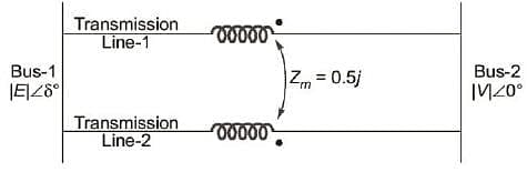
In the figure shown, self-impedances of the two transmission lines are 1.5 j pu each and 0.5 pu Zm = j is the mutual impedance. Bus voltages shown in the figure are in pu. Given that δ > 0 , the maximum steady state real power that can be transferred in pu from bus-1 to bus-2 is
Correct Answer :
|E| |V|
Solution :
Correct Answer:
Let's analyze the given network to find the equivalent impedance and then the maximum steady-state real power transfer.
1. Network Parameters:
We are given two parallel transmission lines with mutual coupling. From the question and diagram:
- Bus-1 voltage:
- Bus-2 voltage:
- Self-impedance of each line:
- Mutual impedance between the lines:
- The polarity dots on both transmission lines are situated at the receiving-end (Bus-2 side) terminals.
2. Finding the Equivalent Impedance:
Let and be the currents flowing from Bus-1 to Bus-2 through Line-1 and Line-2, respectively. The total current leaving Bus-1 is .
Since currents in both lines flow from the sending end (undotted terminal) to the receiving end (dotted terminal), they both enter the undotted terminals. Hence, the mutual coupling voltage aids the self-induced voltage.
Writing the voltage drop equations for both transmission lines:
Since the left-hand sides are equal:
Since , we must have:
Substituting this back into the voltage drop equation:
This allows us to find the equivalent impedance () between Bus-1 and Bus-2:
Therefore, the equivalent line reactance is .
3. Maximum Steady-State Real Power Transfer:
The real power transferred from Bus-1 to Bus-2 is given by the power-angle relation:
The maximum steady-state real power transfer () occurs when :
Access expert-curated educational resources and study materials—completely free.
Create, conduct, and manage professional online assessments with Mindyard. Perfect for teachers and institutes.
Copyright © 2026 Mindyard. All Rights Reserved.