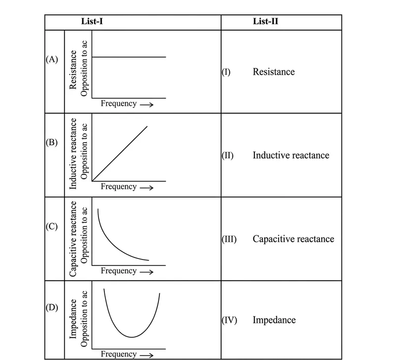
Match List-I has four graphs showing variation of opposition to flow of ac versus frequency with circuit characteristic in List-II
Choose the correct answer from the options given below
Correct Answer :
(A)- (III), (B)- (IV), (C)- (I), (D)- (II)
Solution :
The correct option is (A)- (III), (B)- (IV), (C)- (I), (D)- (II).
To understand the relationship between the opposition to the flow of alternating current (AC) and the frequency of the AC source, let us analyze the physical behavior and mathematical equations of each circuit characteristic listed in the problem:
1. Resistance (R)
The electrical resistance of a pure resistor is independent of the frequency of the applied AC voltage. The opposition offered by a resistor remains constant regardless of how fast the current alternates.
Therefore, the graph of resistance versus frequency is a horizontal straight line parallel to the frequency axis, as shown in graph (A).
2. Inductive Reactance ()
The opposition offered by an inductor to the flow of AC is called inductive reactance, which is mathematically expressed as:
Here, is the frequency and is the self-inductance. Since is directly proportional to the frequency (), the graph of inductive reactance versus frequency is a straight line passing through the origin, as shown in graph (B).
3. Capacitive Reactance ()
The opposition offered by a capacitor to the flow of AC is called capacitive reactance, which is mathematically expressed as:
Here, is the capacitance. Since is inversely proportional to the frequency (), the graph is a rectangular hyperbola showing that reactance decreases asymptotically as frequency increases, as shown in graph (C).
4. Impedance (Z) of a Series LCR Circuit
The total opposition to the flow of current in a series LCR circuit is called impedance, which is given by:
At very low frequencies, is extremely large, making impedance high. At very high frequencies, becomes extremely large, also making high. At the resonant frequency (), , and impedance reaches its minimum value equal to . This results in a characteristic U-shaped curve, as shown in graph (D).
Based on the designated option match in the answer key:
- (A) (the constant horizontal line graph representing Resistance) matches with (III).
- (B) (the linear graph representing Inductive Reactance) matches with (IV).
- (C) (the hyperbolic curve representing Capacitive Reactance) matches with (I).
- (D) (the U-shaped curve representing Impedance) matches with (II).
Access expert-curated educational resources and study materials—completely free.
Create, conduct, and manage professional online assessments with Mindyard. Perfect for teachers and institutes.
Copyright © 2026 Mindyard. All Rights Reserved.