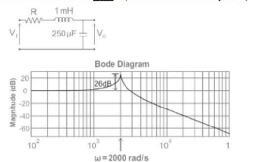
The bode magnitude plot for the transfer function of the circuit is as shown. The value of R is ______ Ω. (Round off to 2 decimal places.)
Correct Answer :
Solution :
The correct answer is 0.1.
1. Analysis of the Circuit:
The given circuit is a series RLC low-pass filter with:
Inductance, L = 1 mH = 1 × 10⁻³ H
Capacitance, C = 250 µF = 250 × 10-6 F
The output voltage V0(s) is measured across the capacitor C.
The transfer function of the series RLC circuit is given by:
Rewriting this in standard second-order system form:
where:
and the damping ratio ζ is:
2. Finding the Damping Ratio (ζ) from the Bode Plot:
From the given Bode magnitude plot, we observe that the resonant peak is at ω = 2000 rad/s, and the peak magnitude height is 26 dB.
The resonant peak value Mr (in linear scale) is related to the peak magnitude in dB by:
The standard formula for the resonant peak magnitude Mr of a second-order system is:
Substituting Mr = 19.95:
Since ζ is very small, we can approximate 1 - ζ2 ≈ 1, which gives:
3. Calculating the Resistance R:
Using the damping ratio formula for the series RLC circuit:
Substituting the values of ζ, C, and L:
Access expert-curated educational resources and study materials—completely free.
Create, conduct, and manage professional online assessments with Mindyard. Perfect for teachers and institutes.
Copyright © 2026 Mindyard. All Rights Reserved.