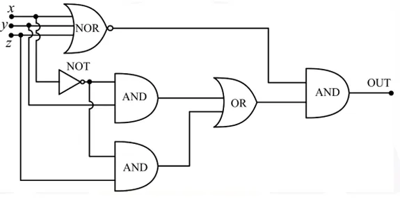
The digital circuit shown has 3 inputs (x,y, and z). The simplified logical expression for the output (OUT) is:
Correct Answer :
0
Solution :
The correct option is 0.
To find the simplified logical expression for the output (OUT), we can trace the inputs through each logic gate shown in the circuit diagram step-by-step.
Step 1: Determine the output of the NOR gate
The top gate is a 3-input NOR gate with inputs x, y, and z. The boolean expression for the output of this NOR gate is:
Using De Morgan's Law, this can be simplified as:
Step 2: Trace the paths through the NOT and AND gates
The input x is connected to the input of a NOT gate. The output of this NOT gate is:
This inverted signal is then fed into one of the inputs of both AND gates below it:
1. The first (upper) AND gate has inputs and y. Its output is:
2. The second (lower) AND gate has inputs and z. Its output is:
Step 3: Determine the output of the OR gate
The outputs of these two AND gates are connected to the inputs of an OR gate. The output of this OR gate is:
Factoring out , we get:
Step 4: Find the final output (OUT)
The outputs of the NOR gate and the OR gate are the inputs to the final AND gate. Therefore, the final output expression is:
Substituting the expressions we derived:
Expanding the terms inside the expression gives:
Using the Boolean algebra identities , , and , we simplify the terms:
1. First term:
2. Second term:
Substituting these simplified terms back into the output equation yields:
Thus, the simplified logical expression for the output of the circuit is 0.
Access expert-curated educational resources and study materials—completely free.
Create, conduct, and manage professional online assessments with Mindyard. Perfect for teachers and institutes.
Copyright © 2026 Mindyard. All Rights Reserved.