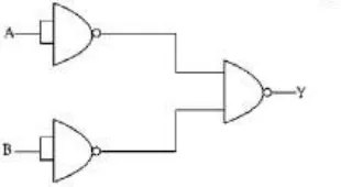
The given combination represents the following gate:
Correct Answer :
OR
Solution :
The correct option is OR.
Step-by-Step Explanation:
By analyzing the provided image, we can identify three NAND gates connected to form a combinational logic circuit. Let's analyze the behavior of this circuit step-by-step:
1. Analyzing the First (Top-Left) NAND Gate:
The inputs of this NAND gate are shorted (tied together) to a single input terminal A.
When the inputs of a NAND gate are tied together, it functions as a NOT gate.
Therefore, the output of this gate is the complement of A:
2. Analyzing the Second (Bottom-Left) NAND Gate:
Similarly, the inputs of this NAND gate are tied together to a single input terminal B, making it act as a NOT gate.
The output of this gate is the complement of B:
3. Analyzing the Third (Right) NAND Gate:
The outputs from the first two gates, and , serve as the inputs to this third NAND gate.
The output of a NAND gate is the complement of the product (AND operation) of its inputs. Therefore, the final output Y is given by:
4. Simplifying the Output using De Morgan's Law:
According to De Morgan's theorem, the complement of a product is equal to the sum of the complements:
Applying this to our expression where and :
Since a double complement cancels out ( and ), the expression simplifies to:
This is the standard Boolean algebraic expression for a two-input OR gate.
5. Truth Table Verification:
We can verify this result by looking at all possible combinations of inputs:
• If , : then , ⇒
• If , : then , ⇒
• If , : then , ⇒
• If , : then , ⇒
The output matches the truth table of a standard OR logic gate.
Access expert-curated educational resources and study materials—completely free.
Create, conduct, and manage professional online assessments with Mindyard. Perfect for teachers and institutes.
Copyright © 2026 Mindyard. All Rights Reserved.