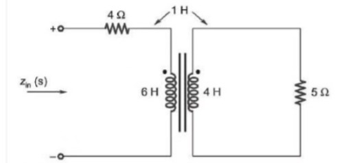
The input impedance, Zin (s), for the network shown is
Correct Answer :
Solution :
The correct answer is:
Step-by-Step Explanation:
Refer to the circuit diagram shown below:
Based on the circuit, we have the following network components and values:
- A primary loop with a resistor of 4 Ω in series with an inductor of self-inductance 6 H.
- A secondary loop with an inductor of self-inductance 4 H in series with a resistor of 5 Ω.
- The mutual coupling between the two inductors is M = 1 H.
- Dot markings representing the polarity of the mutually coupled coils are located at the top terminals of the 6 H and 4 H coils.
Let's define the currents in the s-domain for both loops:
- Let be the clockwise current in the primary loop, entering the dotted terminal of the 6 H inductor.
- Let be the clockwise current in the secondary loop. Following a clockwise path, this current enters the undotted terminal of the 4 H inductor and leaves from its dotted terminal.
Because the primary current enters the dotted terminal of the primary inductor while the secondary current leaves the dotted terminal of the secondary inductor, the mutual inductance induces voltages of opposite polarity. Thus, the mutual coupling term will have a negative sign in the mesh equations.
Now, let's write the mesh equation for the primary loop (Mesh 1):
Simplifying the primary loop equation:
(Equation 1)
Next, let's write the mesh equation for the secondary loop (Mesh 2):
Simplifying the secondary loop equation:
Solving for :
(Equation 2)
Substitute Equation 2 into Equation 1:
Factor out to find the input impedance :
Combine the terms by finding a common denominator:
Expand the numerator:
Subtracting gives:
Thus, we obtain the input impedance :
Access expert-curated educational resources and study materials—completely free.
Create, conduct, and manage professional online assessments with Mindyard. Perfect for teachers and institutes.
Copyright © 2026 Mindyard. All Rights Reserved.