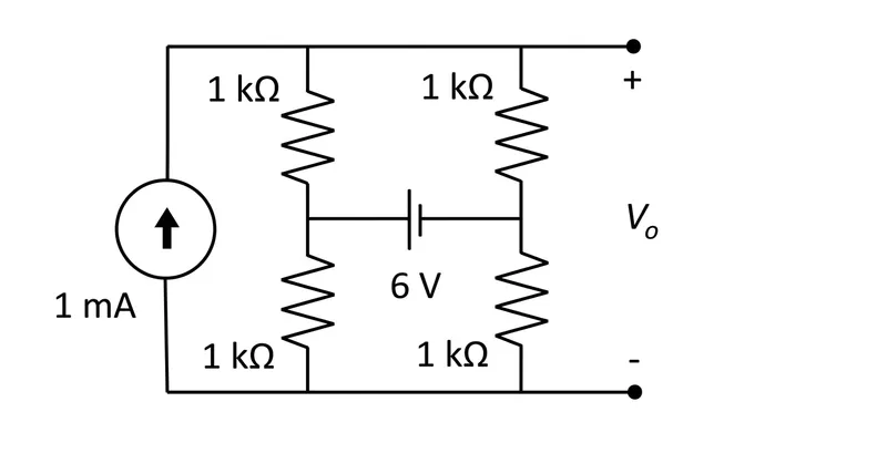
The output voltage V (in Volt) for the network given in the Figure is . (rounded off to two decimal places)
Correct Answer :
Solution :
The correct answer is 1.00.
Step-by-step Explanation:
Let us analyze the given circuit diagram by labeling the nodes and applying Kirchhoff's Current Law (KCL):
1. Let the bottom wire be the reference node (Ground, ).
2. The top wire is at the potential with respect to the reference node, which represents the output voltage we need to find.
3. Let the node between the two left resistors be node at node voltage .
4. Let the node between the two right resistors be node at node voltage .
5. A independent voltage source is connected between node and node with the positive terminal at node , giving:
1. Applying KCL at the bottom node (Ground, 0 V):
The current source of is connected between the bottom wire and the top wire, drawing current out of the bottom node. The two bottom resistors are connected to this reference node. Applying KCL at the bottom node:
2. Applying KCL at the top node (Vo):
The current source injects into the top node. The current leaves the top node through the two top resistors connected to nodes and :
3. Solving for Vo:
Substitute the value of from KCL at the bottom node into the top node equation:
Access expert-curated educational resources and study materials—completely free.
Create, conduct, and manage professional online assessments with Mindyard. Perfect for teachers and institutes.
Copyright © 2026 Mindyard. All Rights Reserved.