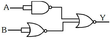
The output (Y) of the given logic gate is similar to the output of an/a
Correct Answer :
AND gate
Solution :
Correct Option: AND gate
To determine the behavior of the given logic circuit, let us analyze each gate component from left to right as shown in the image:
1. Top Gate (Input A):
The top gate is a NAND gate with its inputs shorted together. When the inputs of a NAND gate are connected together, it functions as a NOT gate. Therefore, for an input , the output of this gate is:
2. Bottom Gate (Input B):
The bottom gate is a NOR gate with its inputs shorted together. Similar to a NAND gate, when the inputs of a NOR gate are connected together, it functions as a NOT gate. Therefore, for an input , the output of this gate is:
3. Final Output Gate (Y):
The outputs and are fed as inputs into the final NOR gate. The output of a NOR gate is the logical NOR of its two inputs:
Substituting the values of and into this expression:
4. Simplifying using De Morgan's Laws:
De Morgan's first theorem states that the complement of a sum is equal to the product of the complements:
Applying this theorem to our equation:
Using the double negation law ( and ), the expression simplifies to:
The simplified Boolean expression is the output equation of a standard AND gate. Thus, the output of the given logic circuit behaves like an AND gate.
Access expert-curated educational resources and study materials—completely free.
Create, conduct, and manage professional online assessments with Mindyard. Perfect for teachers and institutes.
Copyright © 2026 Mindyard. All Rights Reserved.