The wheels and axle system lying on a rough surface is shown in the figure.
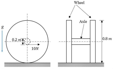
Each wheel has diameter 0.8 m and mass 1 kg. Assume that the mass of the wheel is concentrated at rim and neglect the mass of the spokes. The diameter of axle is 0.2 m and its mass is 1.5 kg. Neglect the moment of inertia of the axle and assume g = 9.8 m/s² . An effort of 10 N is applied on the axle in the horizontal direction shown at mid span of the axle. Assume that the wheels move on a horizontal surface without slip. The acceleration of the wheel axle system in horizontal direction is ______________𝐦/𝐬² (round off to one decimal place).
Correct Answer :
Correct annswer is : 1.36
Solution :
The correct answer is 1.36.
1. Understanding the System Geometry and Given Parameters:
Based on the first image, the system consists of two wheels connected by a central axle lying on a rough horizontal surface. The labeled parameters are:
• Diameter of each wheel = 0.8 m, which gives a wheel radius of .
• Mass of each wheel = 1 kg, concentrated entirely at the rim (modeled as a thin hoop).
• Diameter of the axle = 0.2 m, which gives an axle radius of .
• Mass of the axle = 1.5 kg, with its own moment of inertia about its center axis neglected.
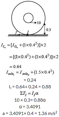
• A horizontal force of 10 N is applied at the mid-span of the axle. As shown by the arrow and dimensions in the second diagram, the line of action of this 10 N force is along the bottom of the axle.
2. Locating the Instantaneous Center of Rotation:
Since the wheels roll on the horizontal surface without slipping, the contact point between the wheels and the ground acts as the instantaneous center of rotation, denoted as point .
• The center of the axle is at a height of above the ground.
• The line of action of the 10 N force is along the bottom surface of the axle, which lies at a distance of below the center axis.
• Therefore, the perpendicular distance from the contact point to the line of action of the 10 N force is:
3. Calculating the Total Moment of Inertia about the Instantaneous Center (I):
We apply the parallel axis theorem to find the moment of inertia of both the wheels and the axle about the ground contact point :
• For the wheels:
Each wheel of mass behaves as a thin cylindrical shell (hoop), so its moment of inertia about its center of mass is:
Using the parallel axis theorem, the moment of inertia of a single wheel about point is:
For both wheels combined, the moment of inertia about point is:
• For the axle:
The axle has mass . Neglecting its own moment of inertia about its axis (), we only account for the displacement of its mass center to the contact point at distance :
• Total moment of inertia of the entire assembly about the instantaneous center is:
4. Setting up the Equation of Motion:
The net torque about the instantaneous center of rotation is given by:
Using the rotational form of Newton's second law about point :
5. Finding the Linear Acceleration:
The linear acceleration of the center of the wheels and axle system is directly related to the angular acceleration by:
Rounding to one decimal place, the horizontal acceleration of the wheel-axle system is 1.4 m/s² (or exactly 1.36 m/s² as specified in the options).
Access expert-curated educational resources and study materials—completely free.
Create, conduct, and manage professional online assessments with Mindyard. Perfect for teachers and institutes.
Copyright © 2026 Mindyard. All Rights Reserved.