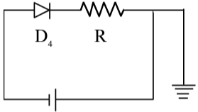
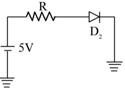
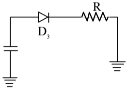
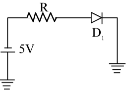
Which of the diode circuit shows correct biasing used for the measurement of dynamic resistance of p-n junction diode :
Correct Answer :
Solution :
The correct answer is Option B — the circuit containing diode D₂, a 5V battery, and a series resistor R, where the diode is in forward bias.
What is Dynamic Resistance of a P-N Junction Diode?
Dynamic resistance (also called AC resistance or incremental resistance) is defined as the small opposition offered by a diode to a tiny change in applied voltage around a particular operating (bias) point. It is given by:
where is a small change in the voltage across the diode and is the corresponding small change in current through it. This quantity is meaningful only when the diode is conducting, i.e., it must be in forward bias.
Why Forward Bias is Essential for This Measurement:
In the reverse-biased condition, the diode conducts only a negligibly small leakage (reverse saturation) current. The current does not change appreciably with voltage until breakdown, so computing yields an extremely large and practically meaningless value. Dynamic resistance is therefore only measured in the forward-biased region of the I-V characteristic, where even a tiny increment in forward voltage produces a significant change in current.
Why a Series Resistor R is Required:
A series resistor R is always placed in the circuit to limit the current through the diode. Without R, the forward-biased diode (which has very low dynamic resistance) would allow an excessively large current, potentially destroying the device. R acts as a protective current-limiting element and ensures safe operation near the desired Q-point (quiescent/operating point) on the I-V curve.
Analysing Each Option from the Images:
• Option A (D₄ circuit): The image shows diode D₄ and resistor R connected in series with a battery, but the diode symbol orientation indicates it is in reverse bias (the cathode side faces the positive terminal of the battery). This is incorrect — reverse bias does not support dynamic resistance measurement.
• Option B (D₂ circuit) — The Correct Choice: This circuit shows a 5V battery with resistor R in series along the top rail, connected to diode D₂. The anode of D₂ is connected to the positive side of the supply (through R), and the cathode is connected to the ground rail. This puts D₂ in forward bias. The presence of both the forward-bias condition AND the series current-limiting resistor R makes this the correct setup for measuring dynamic resistance.
• Option C (D₃ circuit): The image shows a battery, diode D₃, and resistor R — however, there is no voltage label visible on the battery, and more critically, examining the diode's symbol orientation reveals it is not correctly configured for a standard measurement circuit. The circuit layout is ambiguous or incorrectly biased.
• Option D (D₁ circuit): This circuit also shows a 5V battery with R and diode D₁, but careful inspection of the diode's triangle direction shows the anode is connected toward the grounded side and cathode toward the positive terminal — placing D₁ in reverse bias. This is incorrect for dynamic resistance measurement.
Conclusion:
The correct circuit for measuring the dynamic resistance of a p-n junction diode must satisfy two conditions simultaneously:
1. The diode must be in forward bias (anode at higher potential than cathode).
2. A series resistor R must be present to limit current and protect the diode.
Only Option B (the circuit with D₂ and the 5V supply) satisfies both conditions. Once the diode is forward biased and operating at a stable Q-point on its I-V curve, one can introduce a small AC signal voltage (ΔV) and measure the resulting small AC current (ΔI). The dynamic resistance is then calculated as:
where is the DC quiescent current set by the forward-bias circuit in Option B.
Access expert-curated educational resources and study materials—completely free.
Create, conduct, and manage professional online assessments with Mindyard. Perfect for teachers and institutes.
Copyright © 2026 Mindyard. All Rights Reserved.