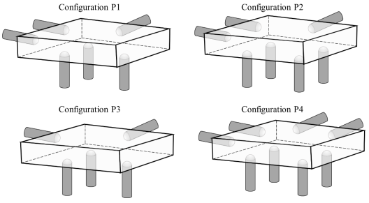
A cuboidal part has to be accurately positioned first, arresting six degrees of freedom and then clamped in a fixture, to be used for machining. Locating pins in the form of cylinders with hemi-spherical tips are to be placed on the fixture for positioning. Four different configurations of locating pins are proposed as shown. Which one of the options given is correct?
Correct Answer :
Configuration P1 arrests 6 degrees of freedom, while Configurations P2 and P4 are over-constrained and Configuration P3 is under-constrained.
Solution :
Correct Option: Configuration P1 arrests 6 degrees of freedom, while Configurations P2 and P4 are over-constrained and Configuration P3 is under-constrained.
Detailed Explanation:
In fixture design, the 3-2-1 locating principle is used to accurately position and restrict the motion of a 3D cuboidal workpiece. A free rigid body in three-dimensional space has six degrees of freedom (DOFs):
Let us analyze each configuration by counting the locating pins on the mutually perpendicular faces of the cuboid:
1. Configuration P1 (The 3-2-1 Principle):
- Bottom Face (Primary Datum Plane): This face is supported by 3 pins. Three points uniquely define a plane, arresting 3 degrees of freedom (translation along the vertical Z-axis, and rotations about the horizontal X and Y axes).
- Back Face (Secondary Datum Plane): This face is positioned against 2 pins. This arrests 2 degrees of freedom (translation along the Y-axis and rotation about the vertical Z-axis).
- Side Face (Tertiary Datum Plane): This face is positioned against 1 pin, arresting 1 degree of freedom (translation along the X-axis).
Thus, the total number of restricted degrees of freedom in Configuration P1 is:
Since exactly 6 independent degrees of freedom are arrested, the part is perfectly and stably constrained without redundancy.
2. Configuration P2:
- Bottom Face: 4 pins are used.
- Back Face: 2 pins are used.
- Side Face: 1 pin is used.
Since 3 pins are mathematically sufficient to define a plane, the 4th pin on the bottom face introduces redundancy, leading to an over-constrained condition.
3. Configuration P3:
- Bottom Face: 3 pins are used.
- Back Face: 1 pin is used.
- Side Face: 1 pin is used.
Here, only 5 pins are used in total. Since 2 pins are needed on the secondary plane to arrest rotation about the vertical axis, using only 1 pin leaves the workpiece free to rotate about the vertical axis. Therefore, Configuration P3 is under-constrained (only 5 DOFs are arrested).
4. Configuration P4:
- Bottom Face: 4 pins are used.
- Back Face: 2 pins are used.
- Side Face: 2 pins are used.
This configuration uses a total of 8 pins, introducing multiple redundant constraints on both the bottom plane (4 pins instead of 3) and the side plane (2 pins instead of 1). Therefore, Configuration P4 is highly over-constrained.
Access expert-curated educational resources and study materials—completely free.
Create, conduct, and manage professional online assessments with Mindyard. Perfect for teachers and institutes.
Copyright © 2026 Mindyard. All Rights Reserved.