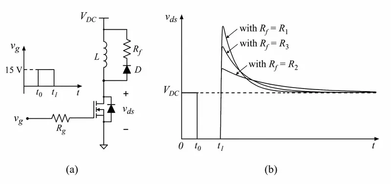
Consider the circuit shown in Figure (a). A gate pulse vg is applied between time instants t0 and t1. After t1, during the MOSFET turn OFF process, it experiences a voltage overshoot. Based on the vds waveforms shown in Figure (b), which one of the following options is correct?
Correct Answer :
R3 > R2 > R1
Solution :
The correct option is R3 > R2 > R1.
Step 1: Analyzing the Circuit during MOSFET Turn-OFF
In Figure (a), when the gate pulse is applied between time and , the MOSFET turns ON and energy is stored in the inductor .
At time , the gate pulse is removed, causing the MOSFET to turn OFF. When the MOSFET turns OFF, the current flowing through the inductor cannot change instantaneously. This forces the freewheeling diode to conduct, establishing a loop containing the DC voltage source , the inductor , and the resistor .
Step 2: Deriving the Peak Drain-to-Source Voltage ()
Applying Kirchhoff's Voltage Law (KVL) around the loop immediately after turn-OFF at , the voltage across the MOSFET is given by:
Also, across the freewheeling branch with resistor and diode , the voltage drop is:
At the instant of turn-OFF (), the current in the inductor reaches its maximum value, . Thus, the maximum (peak) voltage overshoot experienced by the MOSFET is:
Step 3: Comparing the Waveforms
From the peak overshoot formula, we observe that the peak value of is directly proportional to the resistance value :
Looking at the waveform graph in Figure (b):
1. The curve with has the highest peak voltage overshoot.
2. The curve with has an intermediate peak voltage overshoot.
3. The curve with has the lowest peak voltage overshoot.
Therefore, comparing the peak overshoots directly gives:
Rearranging this inequality in terms of leading the sequence:
Access expert-curated educational resources and study materials—completely free.
Create, conduct, and manage professional online assessments with Mindyard. Perfect for teachers and institutes.
Copyright © 2026 Mindyard. All Rights Reserved.