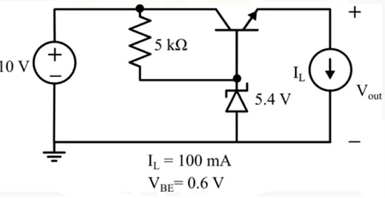
In the linear regulator circuit shown, the base to emitter voltage VBE of the BJT is 0.6 V. The Zener diode clamps the base voltage to 5.4 V. Ignore the bias ing current of the Zener diode and BJT. The maximum possible efficiency of the regulator circuit is _________% (Round off to one decimal place)
Correct Answer :
48.0%
Solution :
Correct Answer: 48.0%
To find the maximum possible efficiency of the regulator circuit, we analyze the circuit diagram which shows:
- Input voltage:
- Zener diode clamping voltage at the base:
- Base-to-emitter voltage of the BJT:
- Load current:
Step 1: Calculate the Output Voltage
The transistor is configured as an emitter follower (common collector), so the output voltage at the emitter is given by:
Substituting the given values:
Step 2: Calculate the Output Power
The power delivered to the load is:
Step 3: Calculate the Input Power
The prompt states that we should ignore the biasing current of the Zener diode and the BJT (making the base current ). Therefore, the input current from the 10 V source is approximately equal to the collector current, which is equal to the emitter current:
Thus, the input power is:
Step 4: Calculate the Efficiency
The efficiency of the regulator is:
Access expert-curated educational resources and study materials—completely free.
Create, conduct, and manage professional online assessments with Mindyard. Perfect for teachers and institutes.
Copyright © 2026 Mindyard. All Rights Reserved.