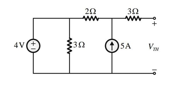
The Thevenin equivalent voltage, VTH , in V (rounded off to 2 decimal places) of the shown below network, is _______.
Correct Answer :
Solution :
The correct answer is 14.
Step-by-Step Explanation:
1. Understand the Circuit Diagram:
From the given circuit diagram, we can observe the following components:
• An independent DC voltage source of 4 V.
• A parallel resistor of 3 Ω connected directly across the 4 V voltage source.
• A series resistor of 2 Ω connected between the node above the voltage source and the middle node.
• An independent current source of 5 A connected to the middle node pointing upwards.
• A resistor of 3 Ω connected in series to the open-circuit output terminals across which the Thevenin equivalent voltage, , is to be measured.
2. Analyze the Open-Circuit Terminals:
Since the terminals for are open-circuited, no current flows through the 3 Ω resistor connected to the positive open terminal.
Therefore, the current through the 3 Ω terminal resistor is zero amperes (0 A), and the voltage across it is 0 V.
Thus, the Thevenin voltage is simply equal to the potential at the node between the 2 Ω resistor and the 5 A current source (taking the bottom reference wire as 0 V).
3. Calculate Node Voltage using Nodal Analysis:
Let the reference node (bottom wire) be at 0 V.
The node to the left of the 2 Ω resistor is directly connected across the 4 V voltage source, so its potential is fixed at 4 V.
Let be the potential at the node above the 5 A current source.
Applying Kirchhoff's Current Law (KCL) at node A (where current leaves the node):
4. Solve for :
Since the open-circuit output voltage is equal to :
Thus, the Thevenin equivalent voltage is 14 V.
Access expert-curated educational resources and study materials—completely free.
Create, conduct, and manage professional online assessments with Mindyard. Perfect for teachers and institutes.
Copyright © 2026 Mindyard. All Rights Reserved.