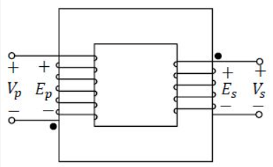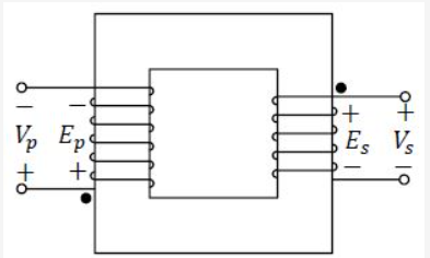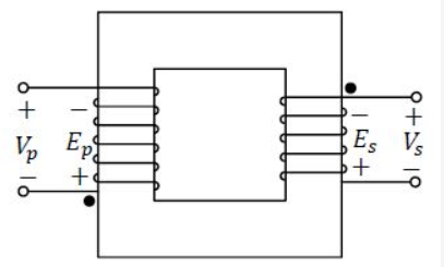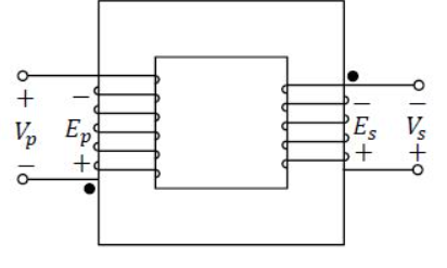
Which one of the following options represents possible voltage polarities in a single phase two winding transformer? Here. Vp is the applied primary voltage. Ep is the induced primary voltage. Vs is the open circuit secondary voltage, and Es is the induced secondary voltage.
Solution :
The correct answer is represented by the first option (Option 1).
To understand why this is the correct configuration of voltage polarities in a single-phase two-winding transformer, we can analyze the relationships between the terminal voltages and the induced electromotive forces (EMFs) on both the primary and secondary sides:
1. Primary Side Voltage and Induced EMF:
On the primary side, the applied terminal voltage is and the induced primary EMF is . Under open-circuit (no-load) conditions, if we neglect the winding resistance and leakage reactance of the primary winding, the terminal voltage is balanced by the self-induced EMF. That is:
Therefore, the reference polarity of the applied primary voltage and the induced primary EMF must be the same (positive at the top terminal and negative at the bottom terminal).
2. Secondary Side Voltage and Induced EMF:
On the secondary side, is the mutually induced EMF in the secondary winding, and is the open-circuit secondary terminal voltage. Since the secondary circuit is open and no current flows, there is no voltage drop across the secondary winding resistance or leakage reactance. Thus, the terminal voltage is directly equal to the induced EMF:
As a result, and must share the identical polarity configuration (positive at the top terminal and negative at the bottom terminal).
3. Analysis of Winding Directions:
By inspecting the winding wraps on the magnetic core:
- The primary winding on the left limb starts at the top terminal and wraps over the front of the core.
- The secondary winding on the right limb starts at the top terminal and wraps behind the core.
- According to Lenz's law and Faraday's law of electromagnetic induction, this physical configuration of the windings determines the relative polarities of the induced voltages. The polarity arrangement shown in Option 1 correctly satisfies the electromagnetic equations where all voltages (, , , and ) are in phase and share positive terminals at the top and negative terminals at the bottom.
Completely free for students. Educators & coaching institutes get 2 months free Pro trial to create tests.
Access unlimited practice questions, detailed step-by-step solutions, and exam study materials — completely free for students.
Create and conduct professional online assessments with AI question generation, tab proctoring, and comprehensive batch management.

Prepare for success in the GATE Electrical Engineering exam with our comprehensive Ultimate Revision Test. Designed for aspirants aiming for top scores, this test covers all key topics in the GATE EE syllabus, including Circuit Theory, Electromagnetic Fields, Power Systems, Electrical Machines, Control Systems, and Analog & Digital Electronics. Our revision test offers a balanced mix of theory-based and application-based questions that will help you assess your understanding and boost your problem-solving skills. With carefully selected questions that mirror the difficulty level of the actual GATE exam, this test will help you identify areas for improvement and fine-tune your exam strategy.

Prepare for GATE 2026 Civil Engineering with the latest question papers, previous year papers, detailed solutions, syllabus, exam pattern, preparation tips, mock tests, and subject-wise study material. Download GATE 2026 CE question papers with solutions in PDF format and boost your preparation for top engineering institutes and PSU recruitment.
Copyright © 2026 Combe Labs Private Limited. All Rights Reserved.