Correct Answer :
Real power loss in Case-1 is more than that in Case-2
Reactive power loss in Case-2 is more than that in Case-1
Real power loss in Case-1 is more than that in Case-2
Real power loss in Case-2 is more than that in Case-1
Reactive power loss in Case-2 is more than that in Case-1
Real power loss in Case-1 is more than that in Case-2
Real power loss in Case-2 is more than that in Case-1
Reactive power loss in Case-1 is more than that inCase-2
Solution :
The correct options/statements are:
1. Real power loss in Case-1 is more than that in Case-2
2. Reactive power loss in Case-2 is more than that in Case-1
Analysis:
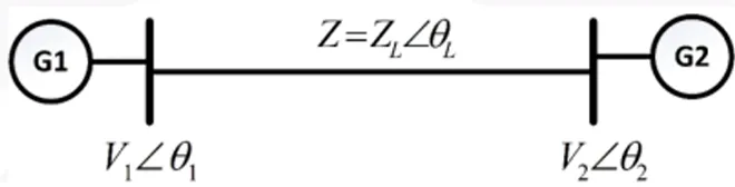
As shown in the single-line diagram, a balanced 3-phase transmission line connects generator G1 (at Bus 1 with voltage phase ) and generator G2 (at Bus 2 with voltage phase ). The transmission line has a series impedance of , where is the resistance and is the reactance of the line.
Using Bus 2 voltage phase as the reference angle (0°), the voltage at Bus 1 is represented as and the voltage at Bus 2 is .
The current flowing through the transmission line is given by Ohm's Law:
The real power loss () and reactive power loss () in the line are calculated using:
Case-1 Evaluation:
Given parameters for Case-1:
- p.u., p.u.
- Line impedance p.u. (purely resistive, so p.u. and reactance p.u.)
- Voltage angle difference
Substituting these values, the line current is:
Using the current value to calculate the losses:
- Real power loss in Case-1:
- Reactive power loss in Case-1:
Case-2 Evaluation:
Given parameters for Case-2:
- p.u., p.u.
- Line impedance p.u. (purely inductive, so p.u. and reactance p.u.)
- Voltage angle difference
Substituting these complex phasor representations:
and
The line current is:
The squared magnitude of this current is:
Using the current value to calculate the losses:
- Real power loss in Case-2:
- Reactive power loss in Case-2:
Comparison of Losses:
1. Real Power Loss:
In Case-1, p.u., while in Case-2, p.u.
Thus, the real power loss in Case-1 is greater than that in Case-2.
2. Reactive Power Loss:
In Case-1, p.u., while in Case-2, p.u.
Thus, the reactive power loss in Case-2 is greater than that in Case-1.
Access expert-curated educational resources and study materials—completely free.
Create, conduct, and manage professional online assessments with Mindyard. Perfect for teachers and institutes.
Copyright © 2026 Mindyard. All Rights Reserved.