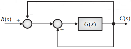
For the block - diagram shown in figure, the transfer function C(s)/R(s) is
Correct Answer :
Solution :
The correct option is:
Step-by-step Explanation:
To determine the overall transfer function of the system shown in the block diagram, we can analyze the signals at each node by tracking the algebraic signs of the summing junctions.
1. Analysis of the First (Leftmost) Summing Junction:
Let the output of the first summing junction be denoted as .
• The reference input signal enters this summing junction with a positive sign ().
• The feedback signal coming from the output enters this summing junction with a negative sign ().
Therefore, the signal equation at this point is:
2. Analysis of the Second (Middle) Summing Junction:
Let the output of the second summing junction (which enters the block ) be denoted as .
• The signal enters this summing junction with a negative sign ().
• Another feedback path from the output enters this summing junction with a positive sign ().
Thus, the equation at the second summing junction is:
3. Substituting the Expression for into :
Replacing with gives:
Distributing the negative sign:
Simplifying the expression:
4. Relating to the Output :
The output is the result of passing the signal through the transfer function block :
Substituting our simplified expression for :
Expanding the term on the right-hand side:
5. Rearranging to find the Transfer Function:
Group all terms containing the output on the left-hand side of the equation:
Factor out :
Finally, solve for the ratio of the output to the input, :
Access expert-curated educational resources and study materials—completely free.
Create, conduct, and manage professional online assessments with Mindyard. Perfect for teachers and institutes.
Copyright © 2026 Mindyard. All Rights Reserved.