
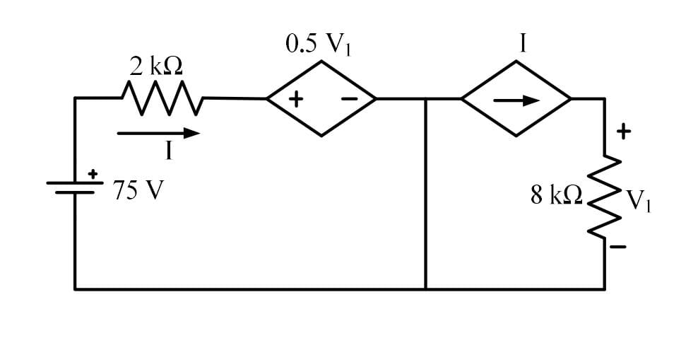
In the circuit shown below, the magnitude of the voltage V1 in volts, across the 8kΩ resistor is _______. (round off to nearest integer)
Solution :
The correct answer is 100.
Circuit Analysis:
Based on the circuit diagram:
The circuit consists of:
- An independent DC voltage source of 75 V.
- A 2 kΩ resistor in the upper-left branch, through which a current I flows to the right.
- A voltage-controlled dependent voltage source of value 0.5 V1.
- A central vertical path which connects the node after the dependent voltage source directly to the reference (ground) node at the bottom.
- A current-controlled dependent current source of value I, pointing to the right.
- An 8 kΩ resistor in the rightmost branch, across which the voltage is V1 (with the positive terminal at the top).
Step 1: Analyzing the Left Loop using Kirchhoff's Voltage Law (KVL)
Because the node between the dependent voltage source and the dependent current source is connected to the common ground wire via the central vertical short-circuit, the voltage at this node is 0 V.
Applying KVL to this closed loop on the left:
Rearranging this to solve for the current I:
Step 2: Analyzing the Right Loop
The dependent current source is connected in series with the 8 kΩ resistor, meaning it dictates the current flowing through it. A current of I flows downwards through the 8 kΩ resistor.
Using Ohm's Law to relate the voltage V1 to the current I:
Step 3: Solving for V1
Substitute the expression for I from Step 1 into the equation in Step 2:
Simplifying the fraction:
Expanding the brackets:
Adding 2V1 to both sides:
Thus, the magnitude of the voltage V1 across the 8 kΩ resistor is 100 V.
Completely free for students. Educators & coaching institutes get 2 months free Pro trial to create tests.
Access unlimited practice questions, detailed step-by-step solutions, and exam study materials — completely free for students.
Create and conduct professional online assessments with AI question generation, tab proctoring, and comprehensive batch management.

Prepare for success in the GATE Electrical Engineering exam with our comprehensive Ultimate Revision Test. Designed for aspirants aiming for top scores, this test covers all key topics in the GATE EE syllabus, including Circuit Theory, Electromagnetic Fields, Power Systems, Electrical Machines, Control Systems, and Analog & Digital Electronics. Our revision test offers a balanced mix of theory-based and application-based questions that will help you assess your understanding and boost your problem-solving skills. With carefully selected questions that mirror the difficulty level of the actual GATE exam, this test will help you identify areas for improvement and fine-tune your exam strategy.

Prepare for GATE 2026 Civil Engineering with the latest question papers, previous year papers, detailed solutions, syllabus, exam pattern, preparation tips, mock tests, and subject-wise study material. Download GATE 2026 CE question papers with solutions in PDF format and boost your preparation for top engineering institutes and PSU recruitment.
Copyright © 2026 Combe Labs Private Limited. All Rights Reserved.