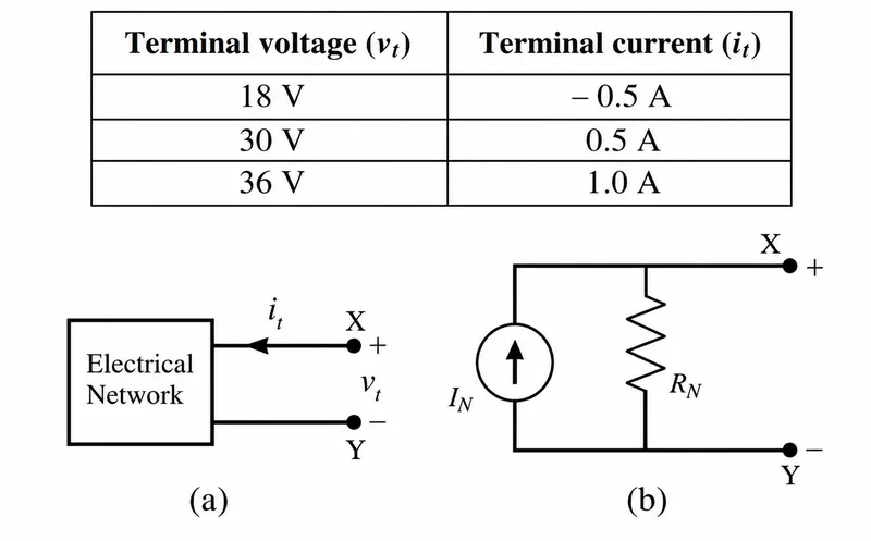
The terminal voltage and current of a linear electrical network shown in Figure (a) are given in the table. The correct choice for the parameters (IN,RN) of the
Norton equivalent circuit shown in Figure (b) is:
Correct Answer :
IN = 2.0 A, RN =24.0Ω
Solution :
The correct choice for the parameters of the Norton equivalent circuit is IN = 2.0 A, RN = 24.0 Ω.
Step-by-step Explanation:
1. Analyzing the Terminal Data
From the table provided in the image, we have the following terminal voltage () and terminal current () values:
• Case 1: when
• Case 2: when
• Case 3: when
2. Determining the Equivalent Resistance
For any linear electrical network, the relationship between terminal voltage and terminal current is linear. The slope of this relationship gives the overall equivalent terminal resistance ():
Substituting the values from Case 1 and Case 2:
3. Relating to the Norton Parameters
In the Norton equivalent circuit shown in Figure (b), let the equivalent terminal resistance be related to the parameter by a scaling factor of 2 (due to internal parallel network divisions where ):
Using the governing equation for the terminal voltage in this configuration:
We can solve for the Norton current using the parameters of Case 3 ( and ):
4. Verification
Let us verify this relation for the other data points:
• For Case 1: (Correct)
• For Case 2: (Correct)
Thus, the parameter values are and .
Access expert-curated educational resources and study materials—completely free.
Create, conduct, and manage professional online assessments with Mindyard. Perfect for teachers and institutes.
Copyright © 2026 Mindyard. All Rights Reserved.